Static Seal Sub-Category Specifications
Five major categories of static sealing products, from basic O-ring sealing to high-pressure back-up ring combined solutions, addressing typical static sealing needs for flange connections, face sealing, and groove installations.

O-ring
Full material portfolio covering both static and dynamic sealing applications. 4,000+ standard sizes in stock (AS568 series + ISO series), with custom non-standard support. Cross-section diameters from 1.0 to 8.4 mm, covering micro-sealing to large-bore flange requirements. Widely used in hydraulic, pneumatic, chemical processing, and automotive flange and face sealing applications. Standard compression rate of 18–25%, with recommended groove design achieving tens of thousands of assembly/removal cycles.
ISO 3601 / AS 568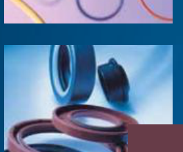
O-ring + Back-up Ring
O-ring combined with a back-up ring effectively prevents extrusion failure under high-pressure conditions. The back-up ring is installed on the low-pressure side, blocking the O-ring's extrusion path into the clearance gap — an essential configuration for high-pressure sealing. PTFE back-up rings for -200~260°C, PEEK back-up rings for above 260°C, and metal back-up rings for 450°C and ultra-high-pressure conditions up to 200 MPa. Recommended when O-ring hardness is ≥70 Shore A.
Pressure-rated selection | Spiral/Skive-cut options available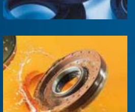
Gaskets
Standard sealing solution for flange connections, featuring three premium material types. PTFE gaskets suit clean/corrosion-resistant applications. Spiral wound gaskets (SS304/316L + flexible graphite) cover medium-temperature and medium-pressure flanges. Metal-graphite composite gaskets balance sealing resilience with high-temperature stability, ideal for chemical piping, heat exchangers, and pressure vessel flange sealing in high-temperature/pressure environments.
ASME B16.20 / EN 1514-1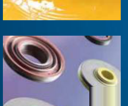
Face Seals
Axial face-sealing design with low outgassing properties suitable for vacuum and clean environments. Commonly used for valve cover sealing, pump end cover sealing, pipe flange faces, and semiconductor/vacuum equipment applications.
Select by cross-section dimensions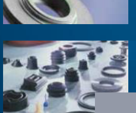
Back-up Rings
Standard O-ring accompaniment, installed on the low-pressure side to prevent the seal ring from extruding into the clearance gap. Available in three material grades — PTFE (standard), PEEK (high-temperature), and Metal (ultra-high-pressure) — for different operating conditions.
Match by O-ring cross-section diameterStatic Seal Quick Selection Guide
Quickly identify the right static seal type based on operating parameters, covering four core decision dimensions: temperature, pressure, media, and installation space.
| Sealing Application Scenario | Recommended Seal Type | Recommended Material | Key Basis |
|---|---|---|---|
| General Flange/Cover Seal (T≤120°C, P≤10MPa) |
O-ring | NBR 70 Shore A | Cost-Optimized |
| High-Temp Fuel/Chemical Media (120°C<T≤230°C) |
O-ring / Gasket | FKM (Viton® Grade) | Chemical Compatibility |
| High-Pressure Hydraulic Fittings (P>15MPa) |
O-ring + Back-up Ring | NBR/FKM + PTFE Back-up Ring | Anti-Extrusion Essential |
| Large-Bore Flange Sealing (DN>200) |
Gasket (Spiral Wound/Graphite) | SS304 + Flexible Graphite | Economical for Large Sizes |
| Vacuum / Clean Environment | Face Seal / O-ring | FKM / FFKM / VMQ | Low Outgassing Required |
| Food / Pharmaceutical | O-ring / Face Seal | EPDM / VMQ / PTFE | FDA/3A Certified |
| Cryogenic Conditions (T<-50°C) |
O-ring / Face Seal | VMQ (Silicone Rubber) | Low-Temp Flexibility |
| Ultra-High-Pressure Injection (P>100MPa) |
O-ring + Metal Back-up Ring | NBR/FKM + Metal Back-up Ring | Extreme Condition |
O-ring Installation Recommendations
Proper groove design and installation practices can prevent over 80% of early failure issues. Below are the core installation parameters recommended by ANPT industry practice.
Groove Dimension Design
Rectangular grooves are the standard design, with groove width-to-depth ratio W/D ≥ 1.2. For piston seals, recommended groove depth = O-ring cross-section × 0.75–0.80; for rod seals, depth = cross-section × 0.72–0.77. Groove bottom corner radius R0.1–R0.3.
Width/Depth Ratio W/D ≥ 1.2Compression Rate Control
Recommended compression rate for static sealing: 18–25% (upper limit for cross-section < 3 mm); dynamic sealing: 8–14%. Insufficient compression (< 10%) causes low-pressure leakage; excessive compression (> 30%) accelerates stress relaxation and permanent set. Groove fill rate should be controlled at 75–90%.
Compression: 18–25% (Static) | 8–14% (Dynamic)Key Installation Practices
Apply compatible grease before installation. When passing over threads/keyways, guide sleeves must be used. O-ring stretch limited to ID ≤ 5% (max post-installation shrinkage recovery 3%). Twisting or rotating installation is strictly prohibited. After installation, visually confirm the seal ring is centered in the groove without cuts or damage.
ID Stretch ≤ 5% | OD Compression ≤ 3%Seal Storage Recommendations
Elastomeric seals age over time and under environmental exposure. Proper storage can extend effective service life to 5–10 years.
Temperature Control
Storage temperature: 0~25°C, away from heat sources and direct sunlight. Low temperatures (< -10°C) may cause material crystallization and hardening; allow gradual warming to room temperature before use.
Humidity Control
Relative humidity < 65%, avoid condensation. High humidity accelerates rubber hydrolytic aging. PTFE materials require a dry environment to avoid moisture adsorption.
Light-Protected Storage
UV radiation accelerates rubber oxidation and cross-linking degradation. Seals must be stored in opaque containers or original UV-protective packaging, away from light.
Packaging & Stacking
Store unopened in original sealed packaging. Avoid contact with copper/manganese (catalytic aging). O-rings should not be suspended or heavily compressed for extended periods; flat storage or large-radius coiling is recommended.
Shelf Life Management
NBR/FKM/EPDM: 5–7 years; VMQ: 10+ years; FFKM: no significant aging limit. Follow FIFO (First-In, First-Out) inventory management. Trigger re-inspection alert 6 months before expiration.
Avoid
Prohibited near ozone sources (motors, HV equipment). Prohibited contact with organic solvent vapors. Prohibited long-term storage under deformation/stretching conditions.
Materials Engineering Data
Engineering parameter comparison of common elastomers and plastics for static sealing, compiled from Trelleborg TDS datasheets. Covers hardness, tensile strength, elongation at break, compression set, temperature range, and compatible media — key selection dimensions.
| Material | Hardness Shore A | Tensile Strength MPa | Elongation at Break % | Compression Set 100°C/24h | Temperature Range °C | Compatible Media |
|---|---|---|---|---|---|---|
| NBR | 70±5 | ≥10 | ≥250 | ≤25% | -40~120 | Mineral oil, Water-glycol |
| FKM | 75±5 | ≥10 | ≥200 | ≤20% | -20~200 | Fuels, Chemicals, High-temp oil |
| EPDM | 70±5 | ≥10 | ≥250 | ≤25% | -50~150 | Hot water, Steam, Brake fluid |
| VMQ | 60±5 | ≥6 | ≥300 | ≤30% | -60~200 | Hot air, Oxygen |
| PTFE | 55±5 D | ≥25 | ≥300 | — | -200~260 | Full chemical compatibility (except molten alkali metals) |
| PU | 92±2 A | ≥35 | ≥400 | ≤35% | -30~100 | Mineral oil, High wear-resistance |
| FFKM | 75±5 | ≥15 | ≥180 | ≤15% | -20~320 | Full chemical compatibility, incl. strong acids/solvents |
Complete Specification Datasheet
The full static seal specification datasheet includes material cross-reference, dimensional tolerances, compression rate recommendations, and installation groove design data. Supports quick search by media type, temperature grade, and pressure range.
Download Specification Datasheet (PDF)More Sealing Categories
Explore other AIINDUSTRY® sealing categories for a complete sealing solution.